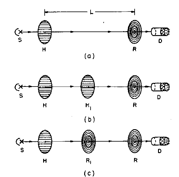
Fig. 13
Schematic diagram showing the three experimental situations considered in the AAD predictions. (a) The photon emerges from the source S, passes through a horizontal linear polarizing filter H, and then through a right circular polariz ing filter R before being detected by a photomultiplier tube D. (b) An intermediate horizontal linear polarizing filter H1 is inserted. (c) An intermediate right circular polarizing filter R1 is inserted. These additional measurements (b and c) are sai d (Albert, 1985) to demonstrate that the photon is simultaneously in a state of linear and circular polarization in the intermediate region.