Officially this was part of a school outreach project, however, truthfully it was a chance to play with the new Pi-zero-W. I must admit i was expecting these to be a little sluggish, but actually they are very usable, ideal for small embedded projects. What i particularly like is that once you get the wifi interface configured you no longer need USB or HDMI connections, simply SSH into the Pi, mount the home directory using SFTP and you good to go, no cables, no clutter, a nice clean development environment. The aim of this project was to show how information can be encoded and communicated electronically. Could of taken this in different directions, but i like the sound of "Morse over IP", a blending of the old and the new.
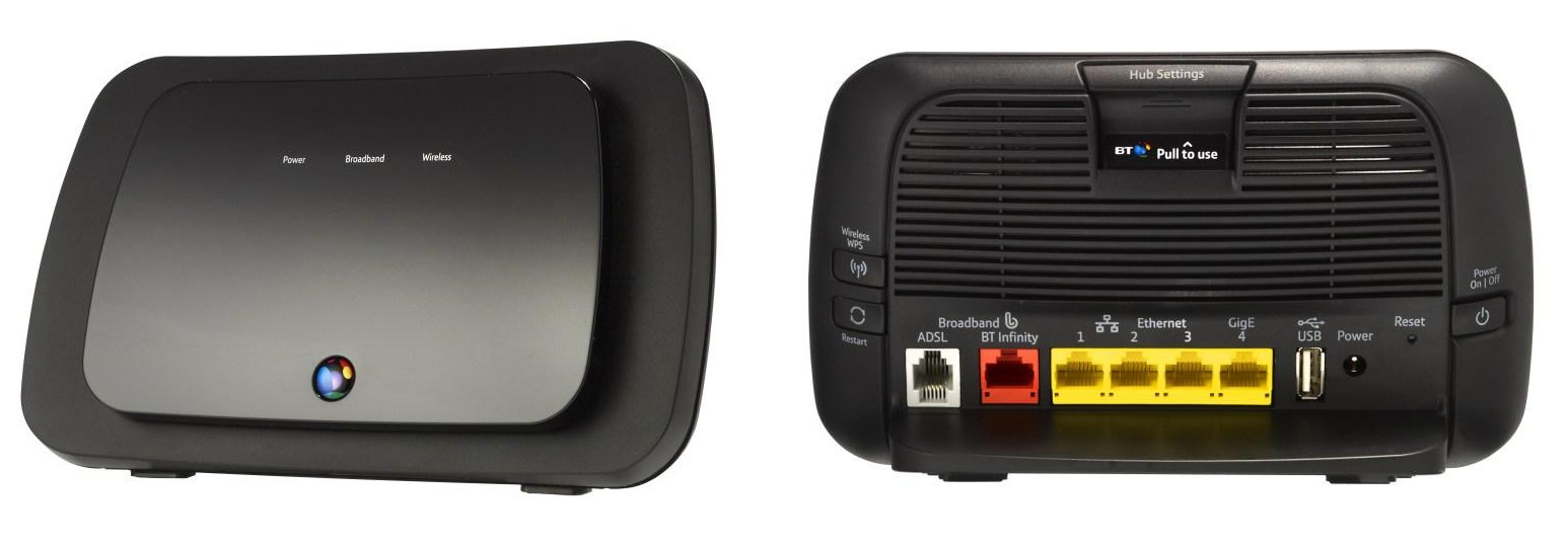
As the title suggests communication between the Morse transmitters-receiver units is wireless, using the Pi-zero-W's Wifi interface. The Wifi network is implemented using an old BT home router, shown in figure 1. This is not connected to a phone line, so the Pi does not have internet access, it is simple acting as a Wifi network hub / DHCP server.
Figure 1 : Old Wifi router
To configure the Wifi network on the Pi the /etc/network/interfaces file used is:
auto lo
iface lo inet loopback

auto wlan0
iface wlan0 inet dhcp
  wpa-conf /etc/wpa_supplicant/wpa_supplicant.conf
The wpa_supplicant.conf file contain the Wifi SSID and password. The easiest way to configure this is to used the wpa_passphrase commandline tool, which generates the WPA PSK passphrase for a specified SSID. Type commands below replacing SSID and PASWORD to match:
sudo su -s /bin/bash
wpa_passphrase SSID PASSWORD > /etc/wpa_supplicant/wpa_supplicant.conf
exit
This will write the text:
network={
	ssid="SSID"
	#psk="PASSWORD"
	psk=HASH
}
Note, remember check that the wpa_supplicant.conf file is only rw for root, if your security minded also delete the password from this file and delete the .bash_history to remove the plain text password. This should auto connect on boot. Final remember to change the default password for the pi, especially if you have SSH enabled. Password changes and enabling SSH can both be achieved by running sudo raspi-config at the commandline. To make configuration easier later need to ensure that the same IP address is assigned to a Morse transmitters-receiver unit each time the lease expires, this is done in the router, as shown in figure 2.
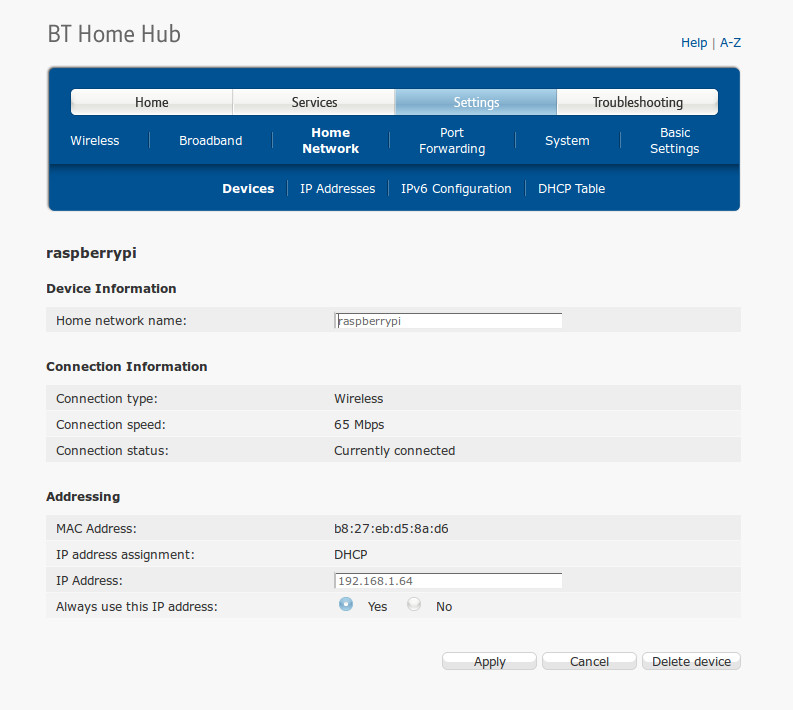
Figure 2 : DHCP table
To ensure that the pi is connected to the router e.g. if the router was not turned on when the pi was booting the following shell script testWifi.sh and cron job runs every 5 minutes.
#!/bin/sh

#testWifi.sh - ping router if no response restart wifi

ping -c1 -w2 192.168.1.254 1> /dev/null 2> /dev/null

if test $? -ne 0
then
	echo wifi down
	/sbin/ifdown --force wlan0
	/sbin/ifup wlan0
else
	echo wifi up
fi
To run this test every 5 minutes type at the commandline sudo crontab -e then add the following:
*/5 * * * * /home/pi/Morse/testWifi.sh 1>> /home/pi/Morse/log.txt 2>> /home/pi/Morse/error.txt
Unfortunately after some testing it was discovered that the router does not remember to assign the same IP address to each Pi i.e. it resets when power cycled :(, therefore needed to discover the IP addresses manually based on a known MAC address. Perhaps there is an easier way, but the shell script findPi.sh below does the job, writing the discovered IP address to the file ip-addr.txt (if found), otherwise writes a blank file.
#!/bin/bash
# findPi.sh - scan IP address from 60 - 80 for matching MAC address

MAX=80

#clean arp table
count=60
while test $count -lt $MAX
do
        ipaddr=192.168.1.$count
        arp -d $ipaddr 1> /dev/null 2> /dev/null
        count=$[$count+1]
done

#find this machines MAC address
mac=`ifconfig wlan0 | grep "HWaddr" | tr -s ' ' | cut -d ' ' -f5`
#echo $mac

#match to known pairs
match=false
if test $mac = "b8:27:eb:d5:8a:d6"
then
        #echo PI-1
        match=true
        PI="b8:27:eb:fa:e7:97"
fi

if test $mac = "b8:27:eb:fa:e7:97"
then
        #echo PI-2
        match=true
        PI="b8:27:eb:d5:8a:d6"
fi

if test $match = true
then
        #echo $PI
	#ping IP address, then test to see if MAC in arp table matches
        count=60
        while true
        do
                ipaddr=192.168.1.$count
                #echo $ipaddr
                ping -c1 $ipaddr 1> /dev/null 2> /dev/null
                count=$[$count+1]

                if test $count -gt $MAX
                then
                        echo > ip-addr.txt
                        exit 0
                fi

                matched_mac=`arp -n | grep $PI | tr -s ' ' | cut -d' ' -f3`
                matched_ip=`arp -n | grep $PI | tr -s ' ' | cut -d' ' -f1`

                if test $matched_mac = $PI
                then
                        echo $matched_ip
                        echo $matched_ip > /home/pi/Morse/ip-addr.txt
                        exit 0
		fi

        done
else
	echo > ip-addr.txt
fi
Originally Morse code was developed for land based electric telegraph systems, around the 1830s. Letter are encoded using a sequence of short and long current pulses, transmitted down a cable, commonly referred to as dots (.) and dashes (-). The sequence of pulses used to encode each letter is based on the frequency of the letter within the English language, as shown in figure 3 i.e. to reduce transmission times commonly used letters were assigned shorter sequences of dots and dashes.
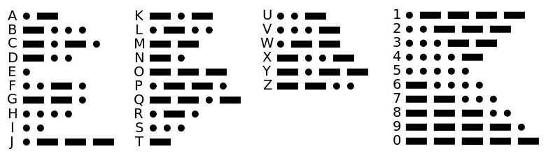
Figure 3 : Morse code
By the 1890s, with the development of underwater cables these techniques enabled inter-continental communications, as shown in figure 4. This illustrates another factor i like about Morse code, it demonstrates the difference between a digital (discrete) and analogue (continuous) signal representation. When transmitting signals down these very long cables the resistance of the cable will reduce the received voltage, therefore, limiting the output (received) current. This could be a problem if an analogue representation is used i.e. the voltage level encodes the information, this reduction in received voltage therefore changes its value. However, as Morse code only uses two states: on/off, even if the received voltage is reduced we can use a simple relay as a discrete "amplifier" to regain the original signal e.g. the received voltage is large enough to energise the coil of a sensitive relay, controlling a pair of contacts that can switch a larger voltage, either making an audible noise or to drive this 'amplified' signal down a further cable i.e. a repeater.

Figure 4 : Telegraph system
Like most people i had played around with Morse code e.g. .../---/..., however, i was not aware that when transmitting these letters there are few more subtleties regarding the length (time) of the dots, dashes and spaces:
When transmitting this information there is no standard unit of time for a dot etc, this is up to the user. When first considering how the Pi based system should be implemented, did consider having code that would identify if the user had keyed a dot or a dash, then transmit a 'standard' dot or dash. However, decided this was needlessly complex. Therefore, implementing Morse over IP is quite simple, all you need to do is transmit the time the Morse key is held down i.e. the length of the pulse entered by the user. This does result in a delay i.e. the receiver only gets the transmitted dot/dash when the key is released, but as these unit will be spread across a room you can't see the transmitting unit, so you don't see the delay :)
UPDATE 16/08/17: this implementation doesn't quite work as specified i.e. if you hold down the key you will get a long space, followed by a long dash which breaks the above timing rules, however, in the context of a teaching aid its still ok, as the receiver can output a short (dot) and a long (dash) tone/light pulse, its just that the inter dot/dash timing isn't quite right.
To start with i used bought in Morse keys, not a cheap items, an example is shown in figure 5. If i was to do this again would look into 3D printing these to save money, very expensive bit of kit. The Morse transmitters-receiver units are based on the Pi zero W, shown in figure 6, communication is wireless using the Wifi network interface. Each Pi is assigned a fixed IP address based on its MAC address, allowing one or more units to be paired together i.e. available hardware units can be configured into separate groups depending on the class/group sizes.

Figure 5 : Morse Key
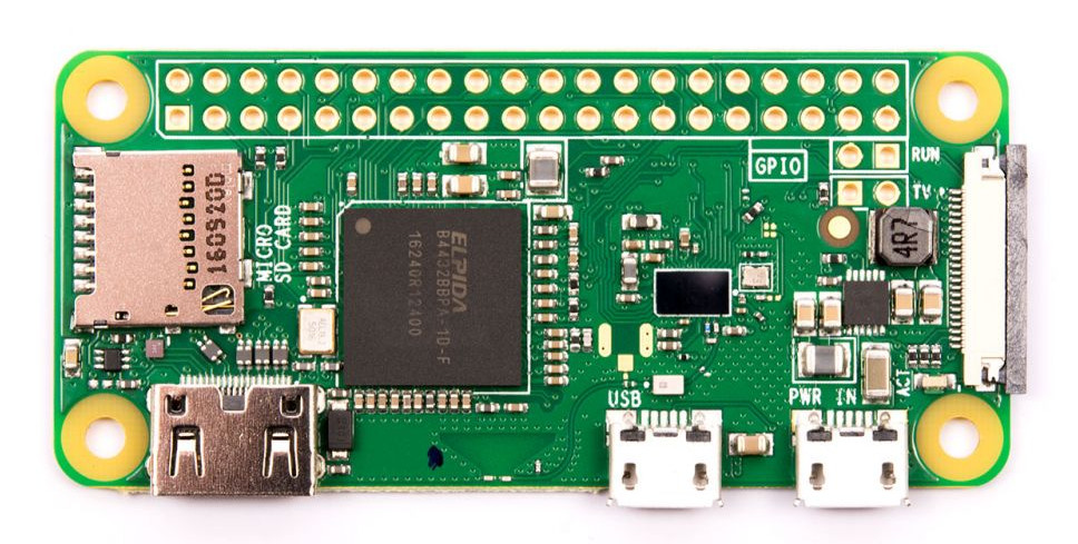
Figure 6 : Pi zero W
To help reduce contact bounce the simple RC circuit shown in figure 7 was used. This also includes the resistors and LEDs used to indicate power, transmitted signal and received signal. The received and transmitted pulses are also used to trigger the pezio electric buzzers i.e. transmitter and receiving software are implemented as two concurrent processes each having a visual (LED) and audible (buzzer) indicator. Could of used a single buzzer, but decided to use two, so that i could keep the transmitter and receiving system completely separated (the two buzzer disks are just mounted in the same cone). Construction of the Morse transmitters-receiver units is shown in figure 8. Connection to the Morse key is via a 3.5mm audio jack, could of used different connectors, just what i had spare. The 3D printed units were based on these units on thingyverse: LINK LINK.
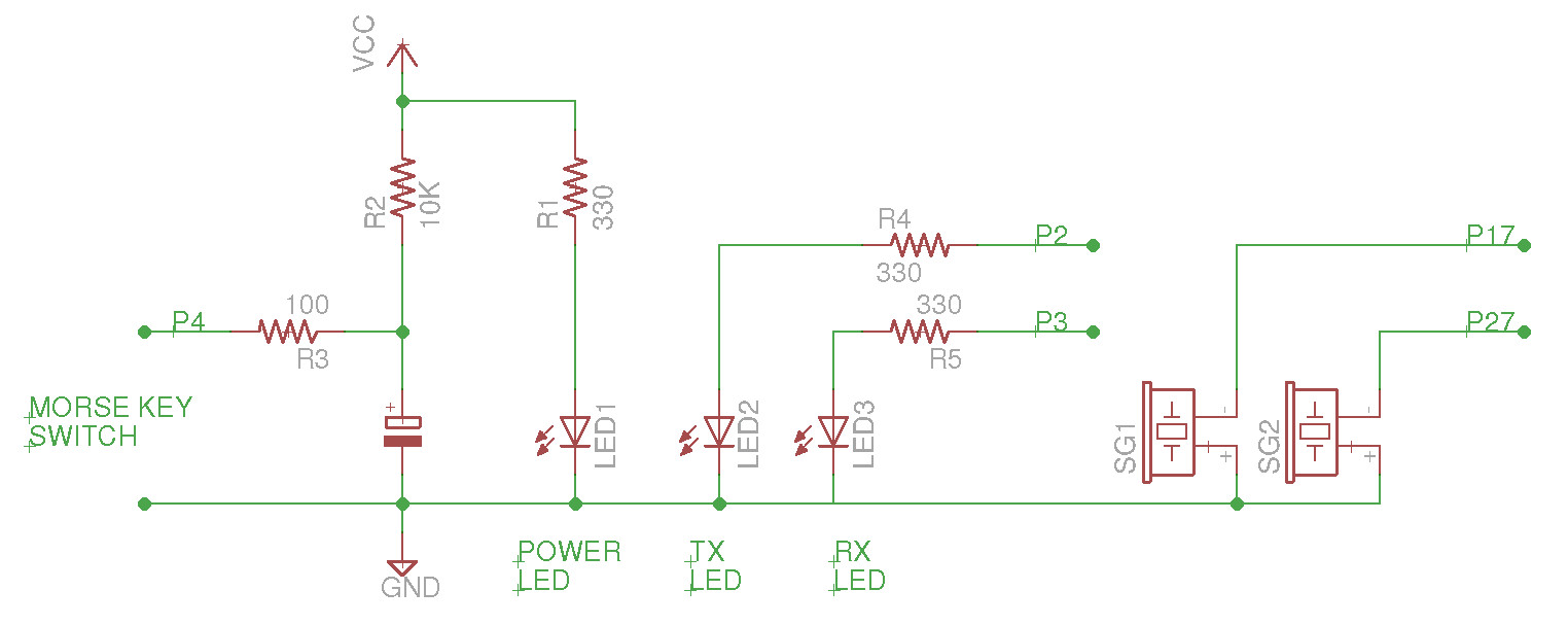
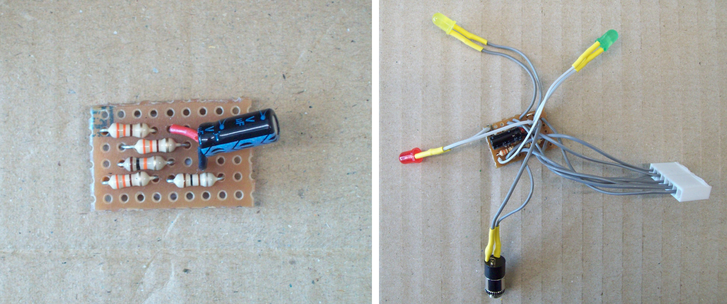
Figure 7 : Interface circuit
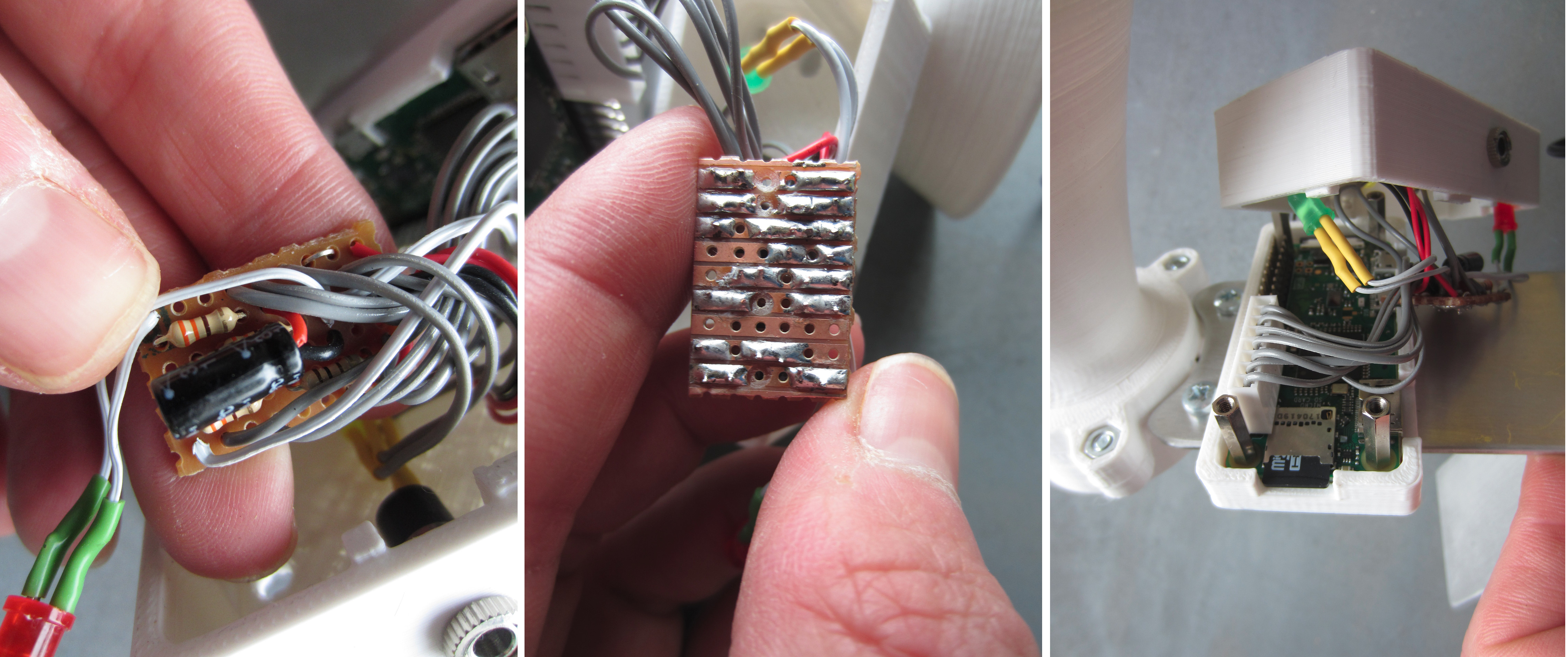
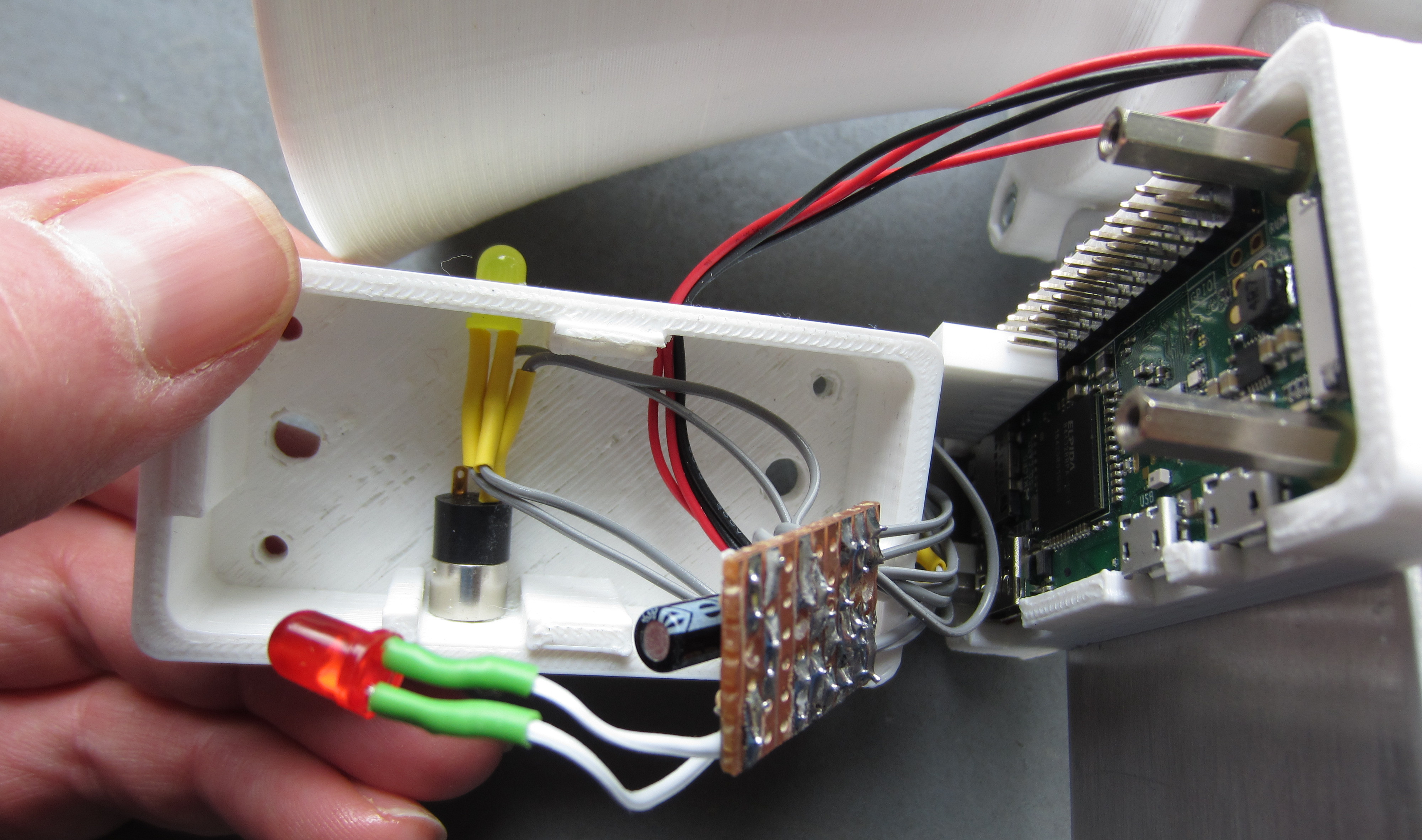
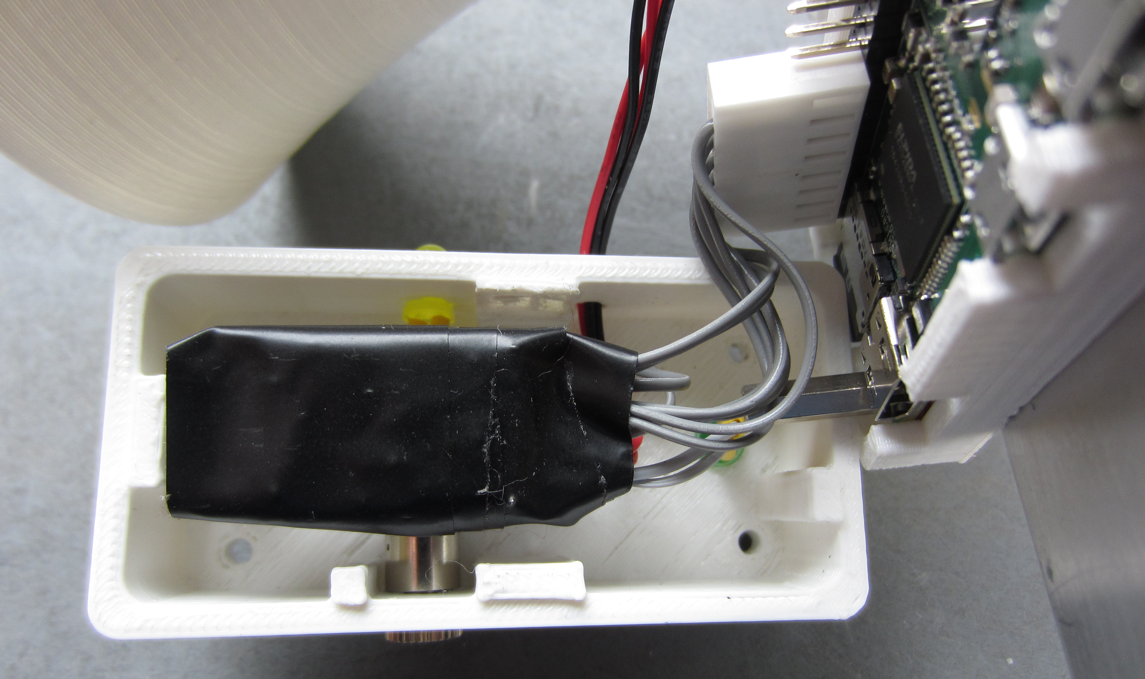
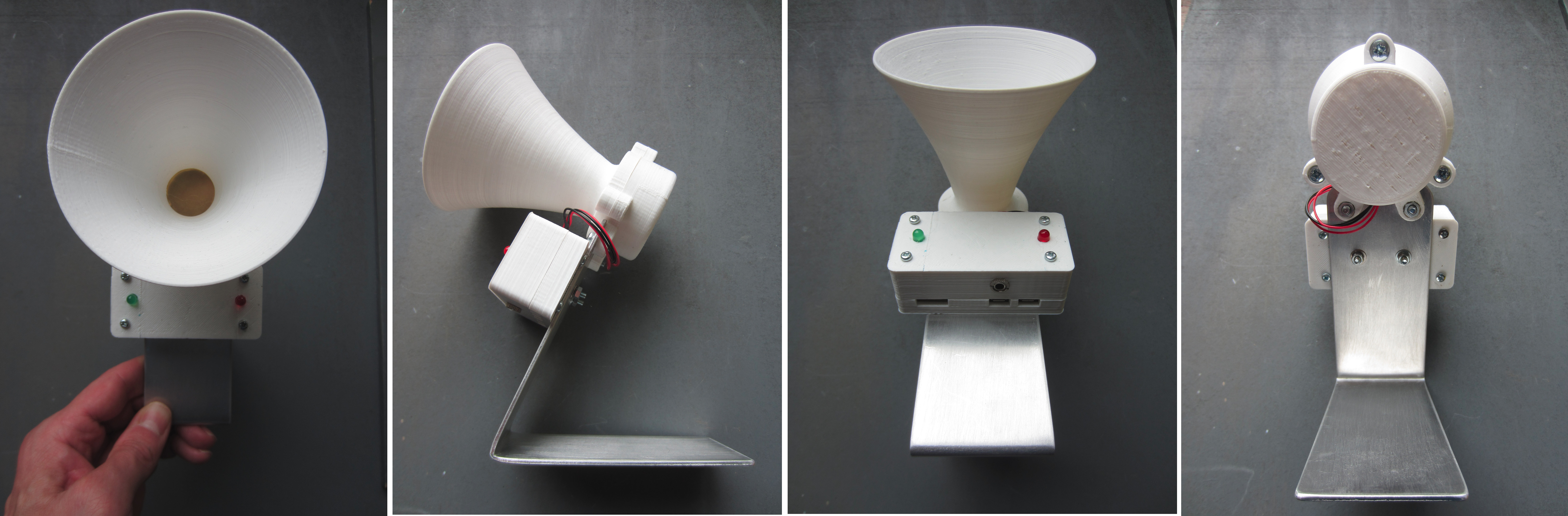
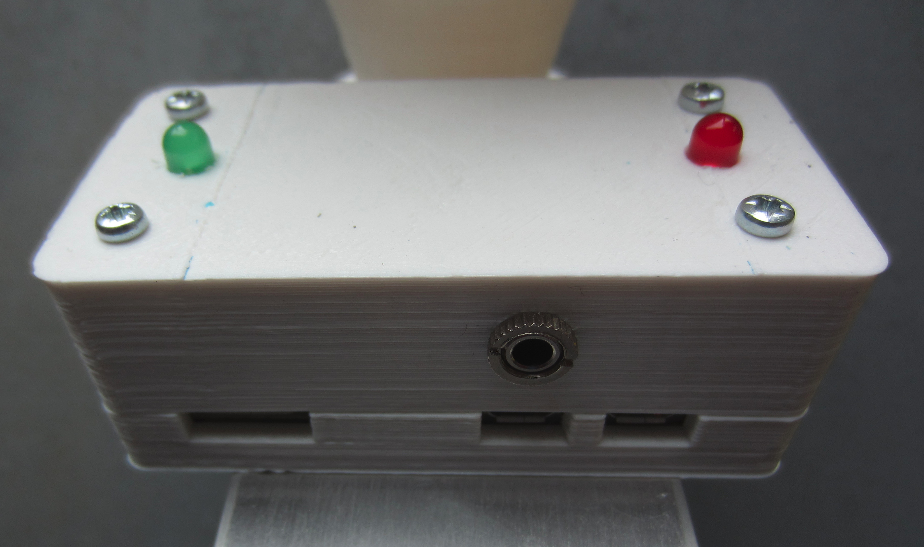
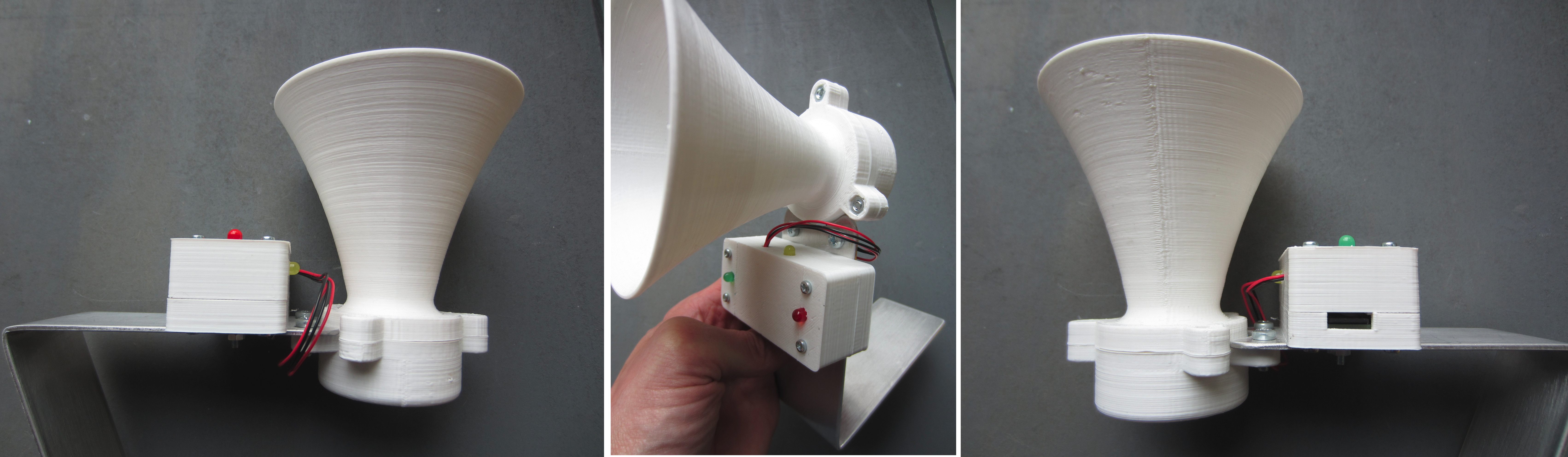
Figure 8 : Morse transmitters-receiver unit
To run the receive (rx.py) and transmit (tx.py) code the following shell script go.sh is used (below). This first calls findPi.sh (previously discussed) which will identify the tx IP address of the other Pi, saving this address to the file ip-addr.txt, whcih is then accessed by the transmit (tx.py) code.
#!/bin/sh
# go.sh - runs rx and tx processes
sleep 10
sudo /home/pi/Morse/findPi.sh
sudo python /home/pi/Morse/rx.py &
sudo python /home/pi/Morse/tx.py &
To run this code at boot the following crontab entry is used (root):
@reboot /home/pi/Morse/go.sh 1>> /home/pi/Morse/log.txt 2>> /home/pi/Morse/error.txt
The python code for the receive (rx.py) and transmit (tx.py) is shown in figures 9 and 10 below. As always a mixer of method, Golden-Rule on coding style and software structure: it was easy for me to program and it works :), i'm sure there are better solutions.
import RPi.GPIO as GPIO
import socket
import time
import sys
import os

RX_BUZZER = 27
RX_LED = 3

# setup GPIO
GPIO.setwarnings( False )
GPIO.setmode( GPIO.BCM )
GPIO.setup( RX_BUZZER, GPIO.OUT )
GPIO.setup( RX_LED, GPIO.OUT )

# power on LED signal
GPIO.output( RX_LED, False )
GPIO.output( RX_BUZZER, False )
time.sleep(5)

# get local machine name
if( len(sys.argv) == 1 ):
  os.system('ifconfig wlan0 | grep "inet\ addr" | cut -d: -f2 | cut -d" " -f1 > /home/pi/Morse/rx-ip.txt')
  f = open('/home/pi/Morse/rx-ip.txt', 'r')
  host = f.read()
  f.close()
else:
  host = str( sys.argv[1] )

port = 9999
print "RX: ", host

# create a socket object
serversocket = socket.socket( socket.AF_INET, socket.SOCK_STREAM )

# bind to the port
serversocket.bind((host, port))

# queue up to 5 requests
serversocket.listen(5)

while True:
  # establish a connection
  clientsocket,addr = serversocket.accept()

  # Receive no more than 1024 bytes
  time_data = clientsocket.recv(1024)
  clientsocket.close()

  #print("Got a connection from %s" % str(addr))
  #print time_data

  loop_count = (int(float(time_data) / 0.002) * 10)
  #print loop_count

  # oscillate RX buzzer
  for i in range( loop_count ):
    GPIO.output( RX_LED, True )
    GPIO.output( RX_BUZZER, True )
    time.sleep(0.001)
    GPIO.output( RX_BUZZER, False )
    time.sleep(0.001)

  GPIO.output( RX_LED, False )
Figure 9 : Receiver code
import RPi.GPIO as GPIO
import socket
import time
import sys
import os

TX_SWITCH = 4
TX_BUZZER = 17
TX_LED = 2

# setup GPIO
GPIO.setwarnings( False )
GPIO.setmode( GPIO.BCM )
GPIO.setup( TX_BUZZER, GPIO.OUT )
GPIO.setup( TX_LED, GPIO.OUT )
GPIO.setup( TX_SWITCH, GPIO.IN, pull_up_down=GPIO.PUD_UP )

GPIO.output( TX_LED, False )
GPIO.output( TX_BUZZER, False )
time.sleep(5)

# get machine name
if( len(sys.argv) == 1 ):
  f = open('/home/pi/Morse/ip-addr.txt', 'r')
  host = f.read()
  f.close()
else:
  host = str( sys.argv[1] )

port = 9999
print "TX: ", host

# wait 100 sec for rx unit to boot
host_ready = False
GPIO.output( TX_LED, True )
for i in range(10):
  response = os.system("ping -c1 -w2 " + host + " > /dev/null 2>&1")
  if response == 0:
    host_ready = True
    print host, 'is up!'
    break
  else:
    print host, 'is down!'

  time.sleep(10)

GPIO.output( TX_LED, False )
start = 0
while True:
  # has button been pressed?
  if( GPIO.input( TX_SWITCH ) == 0):
    # record start time - not really needed
    if( start == 1 ):
      start_time = time.clock()
      start = 2

    # oscillate tx buzzer
    GPIO.output( TX_LED, True )
    GPIO.output( TX_BUZZER, True )
    time.sleep(0.001)
    GPIO.output( TX_BUZZER, False )
    time.sleep(0.001)

  # button not pressed
  else:
    GPIO.output( TX_LED, False )

    # if previously pressed - open socket - tx on time
    if( start == 2 ):
      end_time = time.clock()
      elapse_time = end_time - start_time
      #print "Elapse Time: ", elapse_time
      start = 1

      # connection to RX
      if host_ready:
        clientsocket = socket.socket(socket.AF_INET, socket.SOCK_STREAM)
        try:
          clientsocket.connect((host, port))
          clientsocket.send(str(elapse_time))
          clientsocket.close()
        except socket.error as msg:
          print "Socket Error: %s" % msg
        except TypeError as msg:
          print "Type Error: %s" % msg

    if( start == 0 ):
      start = 1
Figure 10 : Transmitter code
Need to make it a little more robust e.g. what is a MAC address can not be found, what if one of the units is turn off etc. Also need to add support for multiple receivers and transmitters e.g. one transmit and multiple receive etc.

This work is licensed under a Creative Commons Attribution-NonCommercial-NoDerivatives 4.0 International License.
Contact details: email - mike.freeman@york.ac.uk, telephone - 01904 32(5473)
Back