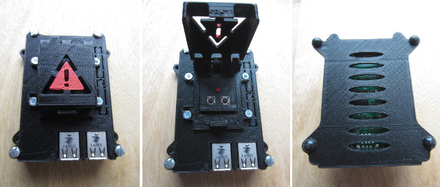
Figure 1 : case
Recently moved over to using a Raspberry pi as a desktop machine, mostly for terminal access (SSH-ing), downloads and torrents etc. Since the introduction of the Pi2/Pi3 and fast SD cards these machines are really quick to boot, and as long as your not looking for a high speed web browser they are very usable, ideal for background type tasks or system / network monitoring etc. My preferred 3D printed case is from Thingiverse, a well designed box with 75mm VESA mounting tabs (Link )(Local ). However, as i sometimes run the Pi headless or use a KVM switch to share the keyboard etc with my main PC, i needed a way to safely shutdown the Pi or reboot it, without having to reconnect a lot of cables. Therefore, expanded this case, adding two external switches and a power on LED, as shown in figure 1.
A protective switch cover, essential for this mission critical system :), was again obtained from Thingiverse (Link )(Local ). To mount the reset and shutdown switches, and mount the power-on LED, knocked up a quick panel, as shown in figure 2. The OpenSCAD and STL files can be downloaded here:(Local ). The switch cover is mounted to the case using four M3x5 countersunk bolts. To allow these to "tap" into the case i used a fine tipped soldering iron to melt an approximate 2.5mm hole. This welded plastic allows you to screw the bolts in, and as the layers are fused you rarely see any splitting / delamination (unless the melted hole was a little too small). The hinge for the switch cover is simply a piece of M3 studding cut to length and screwed in, a little tricky at the end when you don't have anything to hold on to, but doable. Finally, painted the warning triangle with red acrylic paint.
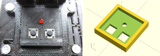
Figure 2 : protective switch cover internal panel

Figure 3 : switches
Still have a bag of switches left over from the stop-frame project, nice switches, a reassuringly firm click. These switches have four legs, as shown in figure 3, to give a larger, more stable solder pad these legs can be folded over as shown in figure 4, implementing a basic normally open, SPST switch. These switches were super-glued into the panel along with a 330 ohm resistor and a 3mm LED. The RESET pins for the Raspberry Pi are located at one edge of the board as shown in figure 5. To reset the Pi you simply short these pins together with a switch. However, this is a hard reset, so is just as bad as pulling out the power, as far as unsaved files and SD cards are concerned, therefore, to allow a more graceful shutdown GPIO pin 4 is used. Using a simple python program this pin is setup as an input with internal pull-ups i.e. default input is a logic 1. A switch is then used to pull this pin low (connecting it to 0V), generating an event i.e. an interrupt, waking the suspended process, which then issues a shutdown command. The wiring and the GPIO pins used are shown in figures 5 and 6. The LED is connected to pins 4 and 6 (through a 330 resistor), the shutdown switch is connected to pins 7 (GPIO4) and 9 (GND).
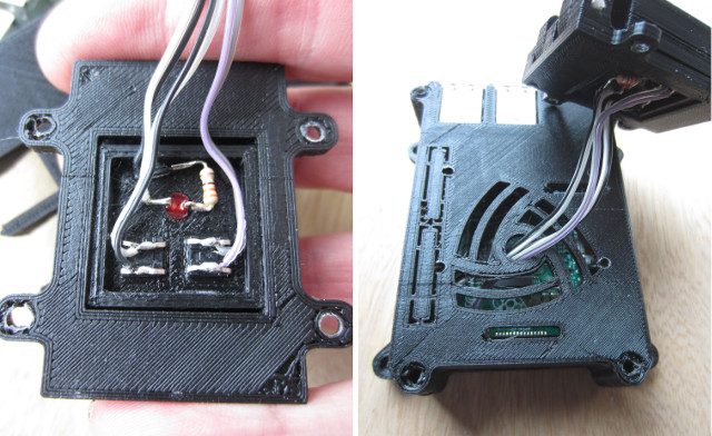
Figure 4 : wiring
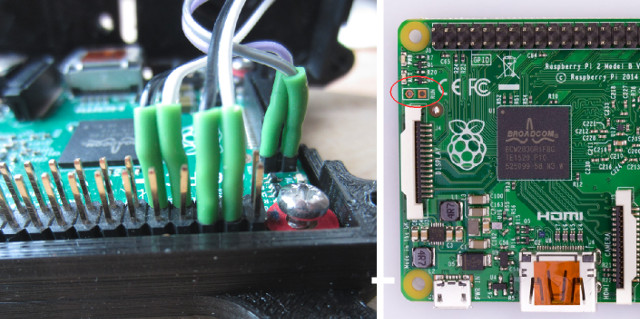
Figure 5 : reset pin
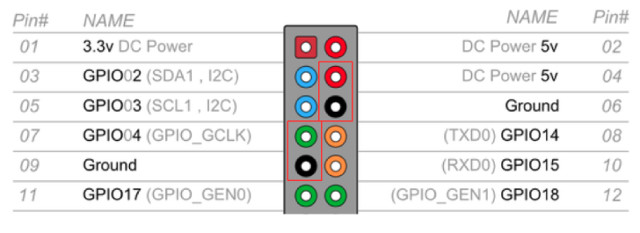
Figure 6 : GPIO header
The python code to implement the shutdown function is shown in figure 7, originally sourced here: (Link ), the key instruction is the wait_for_edge instruction that suspends the process, therefore, not adding to the processor's load. To start this code at boot there are a number of different methods, personally i run this as a cron job, perhaps not the best way from an admin perspective, but it works.
import RPi.GPIO as GPIO
import time
import os

GPIO.setmode(GPIO.BCM)
GPIO.setup(4, GPIO.IN, pull_up_down=GPIO.PUD_UP)

try:
	GPIO.wait_for_edge(4, GPIO.FALLING)
	print("shutdown -h now")
	os.system("shutdown -h now")
except:
	pass

GPIO.cleanup()
Figure 7 : python code: shutdown.py
To define a cron job, open a terminal and type:
sudo crontab -e
Then enter this line:
@reboot /home/pi/bin/go.sh
This will launch the shell script program go.sh from the specified directory. This file then launches the python program which suspends waiting for a falling edge on pin 4 i.e. with internal pull-ups enabled, when the switch is pressed it connects this pin to a logic 0, triggering the shutdown process.
#!/bin/sh
sudo /usr/bin/python /home/pi/bin/shutdown.py
Figure 8 : shell script - go.sh
The final setup is shown in figure 9, an external 16GB USB flash stick is used to store upload and download files, this could be explicitly mounted in /etc/fstab, but Raspian auto mounts this disk on boot to /media/pi/external so left it as is, added a symbolic link to the home directory for easy access. To get information on and off this system simply enable SSH through the raspi-config command, remembering to change the default password. This gives remote access to the system and allows you to mount the its disks, giving simple drag and drop file transfers i.e. no need to install Samba etc.
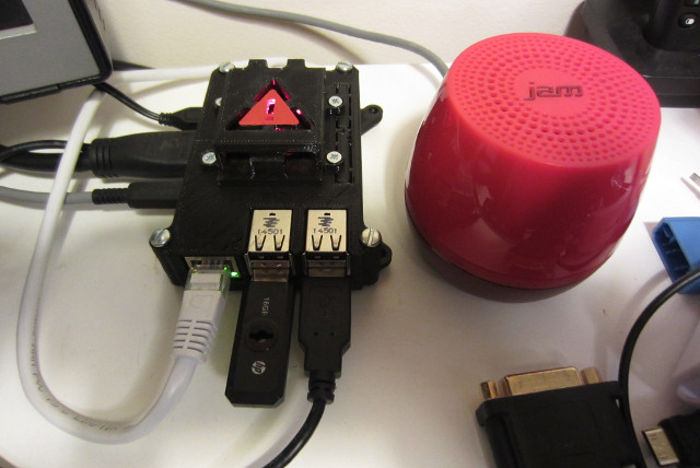
Figure 9 : final system
The shutdown button works nicely, you can see when the Pi has finished its shutdown sequence as the ethernet LEDs turn off. The reset button works as a soft power-on button i.e. after you have shutdown the pi you can turn it back on by pressing the reset button. Attached a small powered speak, connected to the 3.5mm audio out to play music, use espeak to notify events.

This work is licensed under a Creative Commons Attribution-NonCommercial-NoDerivatives 4.0 International License.
Contact details: email - mike.freeman@york.ac.uk, telephone - 01904 32(5473)
Back