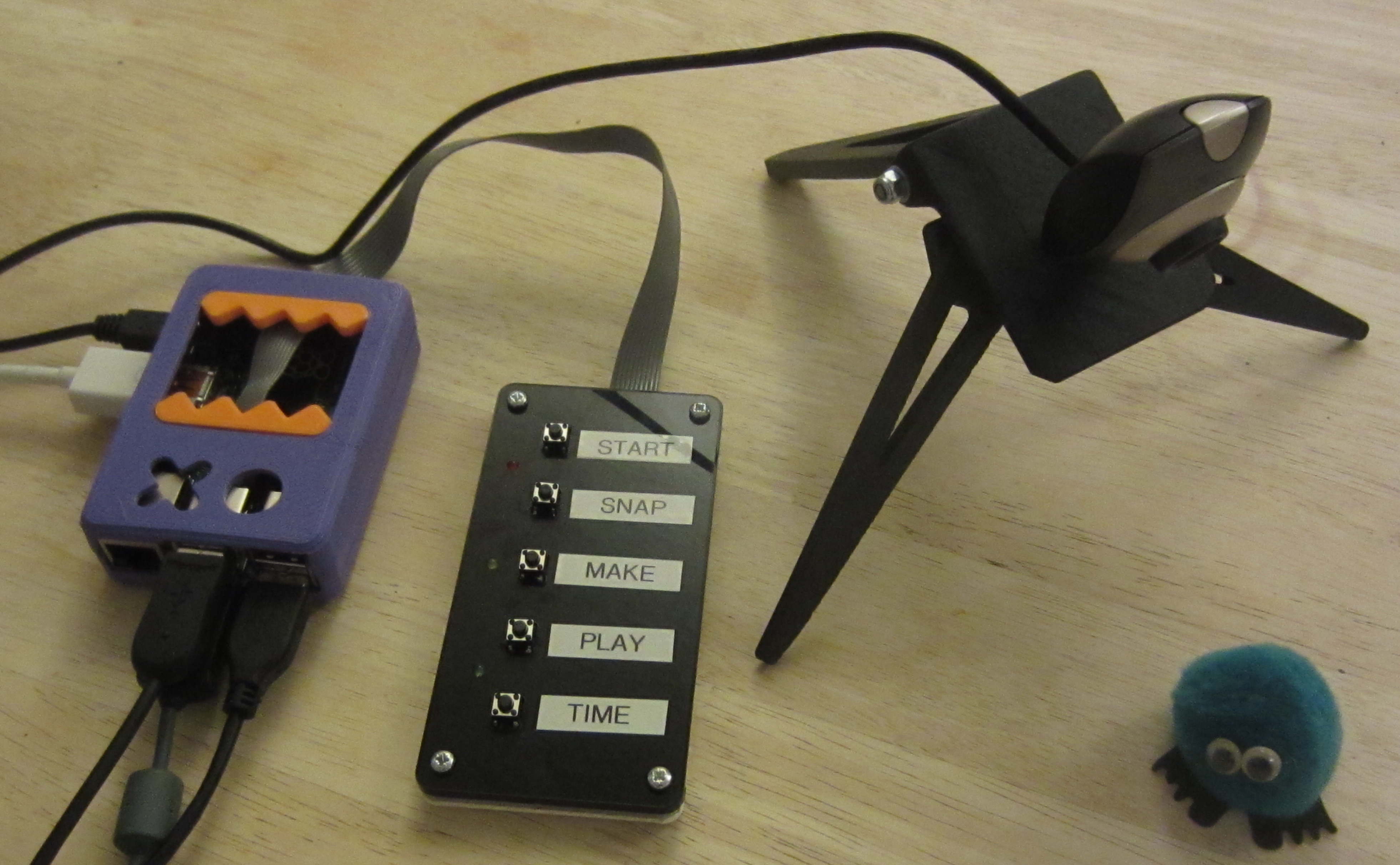
Never know what to get people for Xmas, so decided i would build something. What to build? Decided on a stop frame animation system based around a Raspberry Pi, fun for all the family :). Could of gone for a software biased solution i.e. functions triggered via your mouse/keyboard, but I wanted to actually build something physical, so came up with the idea of an external control pad, as shown in figure 1. The aim here was to have all functions controlled by these switches i.e. resetting the system, taking a picture, generating the video and playing the video etc.
Figure 1 : raspberry pi stop frame animation system
Decision made, need to buy stuff. Looking online I was surprised to see that even older generation raspberry pi are still holding their value, as we now have the Pi 3, i thought the earlier versions would have come down in price. Looking around the web, Ebay and Amazon etc, a B+ model still sells for around £25, however, did spot a few for £15. Web cameras on the other hand are ridiculously cheap, i guess driven by the ubiquitous camera in your mobile phone, a standard VGA 640x480 USB camera costing £3 to £5. Next switches, to be honest not sure how people can sell these on amazon so cheaply and still make a profit, a bag of 50 for £1.19 (including postage), so impressed with this value for money had to include a pic, shown in figure 2 (now need another project to use the other 45 buttons :). Finally, assorted other stuff e.g. plastic, wires, solder etc, as always these are sourced from my bottomless box of bits.
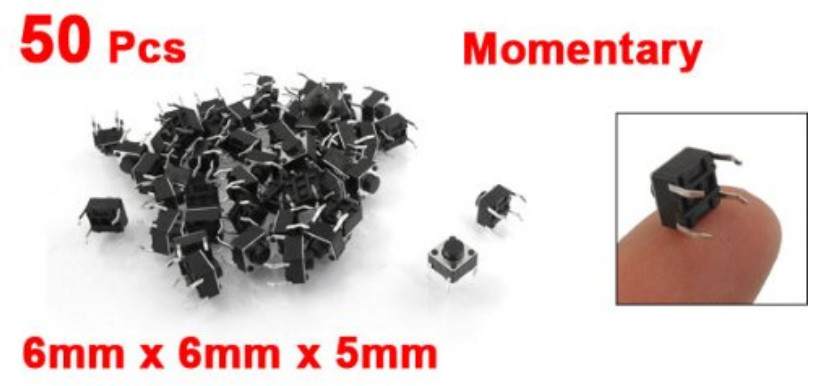
Figure 2 : bargain switches
Interfacing the switches to the Pi, had an old 10 way IDC connector + ribbon cable already made up in the scrap box. If you remove the strain relief strap and file down the connector a little it fits nicely onto the GPIO header. Looking at the GPIO header layout (shown in figure 3), decided to go for the bottom set of pins, this gives access to 0V and eight GPIO lines, an added bonus is that there isn't a danger of exposing +3V or +5V to external short circuits i.e. the switches used in a pull down configuration. The Pi is mounted in a 3D printed box, the original STL files from Thingiverse, (Site), (Link), a fun box. The 10 way IDC connector and ribbon cable are shown in figure 4. Did cut out a little 'slot' from the top lid to make a recess for the ribbon cable to pass through.
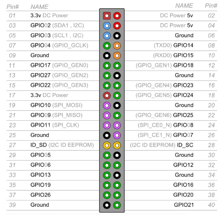
Figure 3 : GPIO header
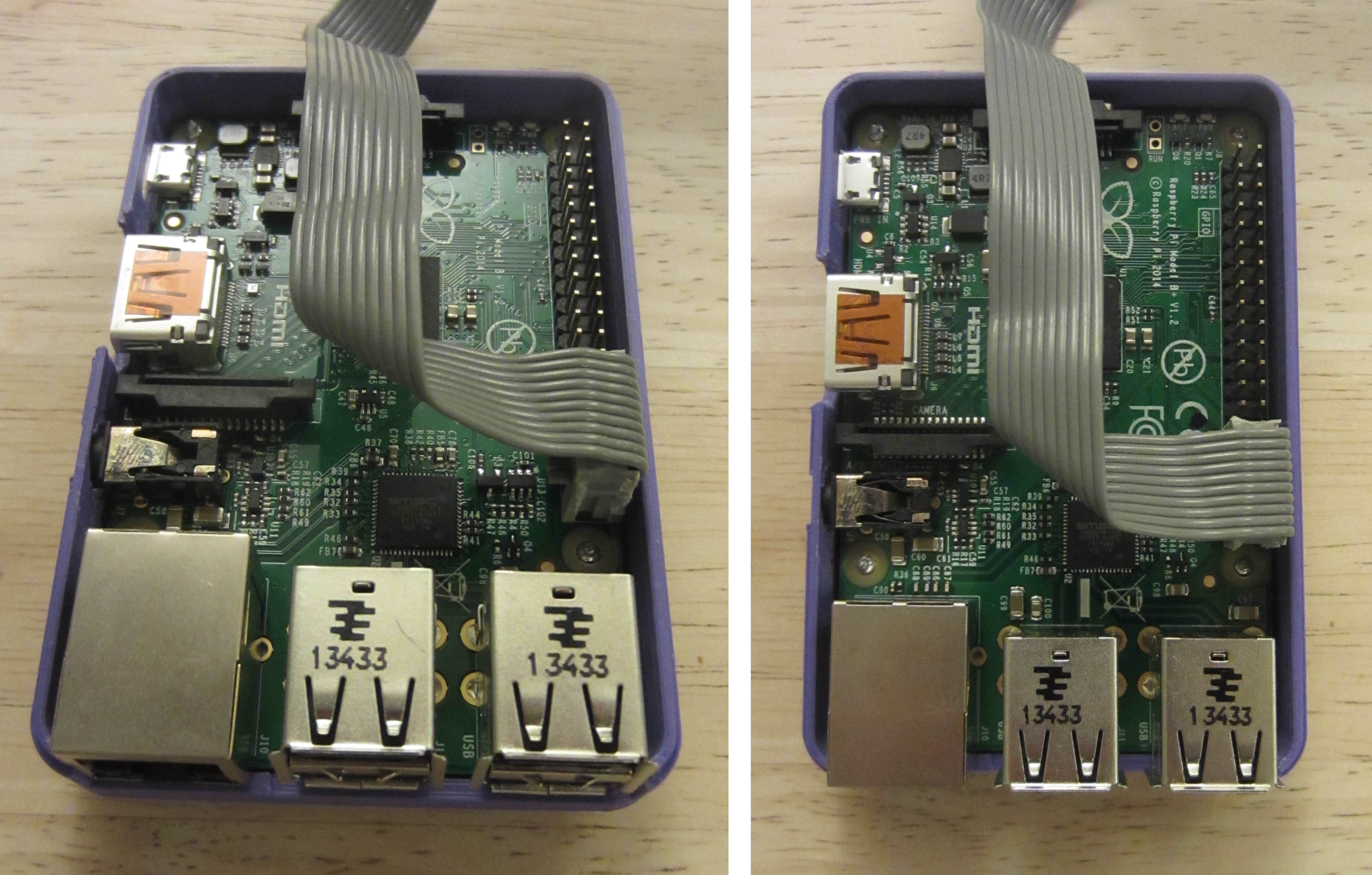
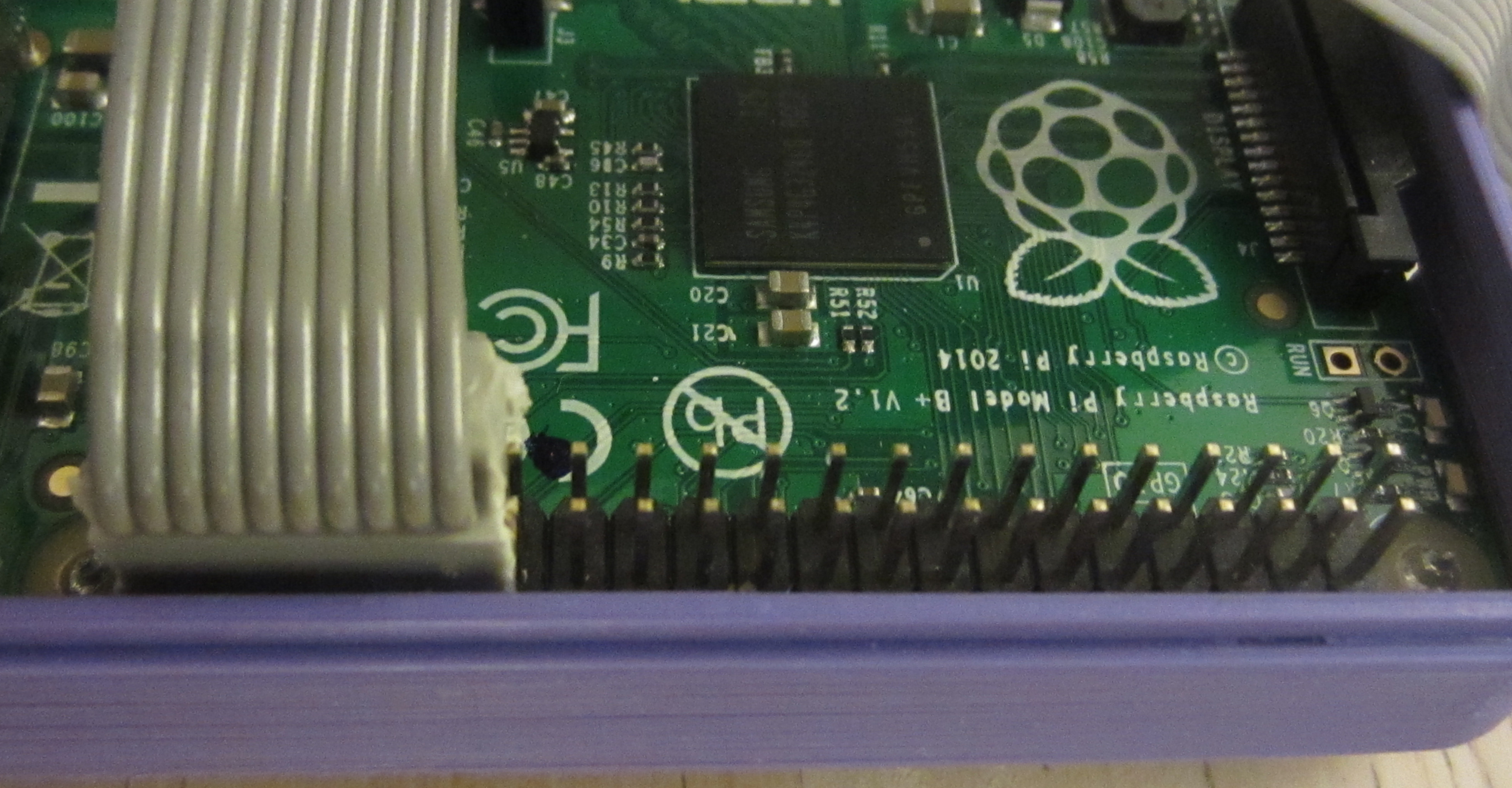
Figure 4 : connector
The control pad has five switches and three LEDs, wired as shown in figure 5. The Eagle CAD files are available here: (Link). Under software control each GPIO pin can be configured to be either an input or output port. When used as an input a 50K ohm pull-up or pull-down resistor can be enabled i.e. the pull-up resistors connected to the switches in figure 5 are internal to the raspberry pi. The 100 ohm resistors could in theory be left out, but personally i don't like to stress the output drivers on the pi i.e. always good to have a current limiting resistor when driving LEDs. I was hoping not to add the capacitors, but during testing i could not remove the switch noise using software methods i.e. contact bounce. In theory the software should of worked, but i was getting a lot of false triggers each time a switch was pressed e.g. it would take two photos each time i pressed the associated button. Therefore, resorted to a cheap and cheerful switch de-bouncer i.e. the CR time constant made up of the 50K ohm pull-up and the 1uF capacitor ensures that any small pulses can not raise the input voltage to a logic '1'. Note, capacitors are a little on the large side, however, 100nF didn't work, ideally would of liked to discharge the capacitor through a small resistor e.g. 100 ohms, to reduce any 'wear' (arcing/sparks) on the switch contacts.
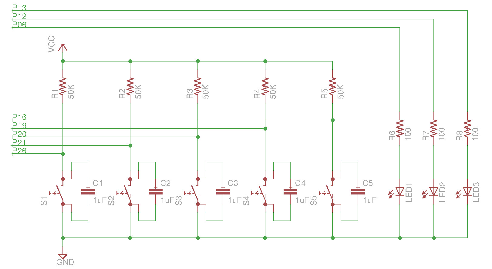
Figure 5 : Wiring
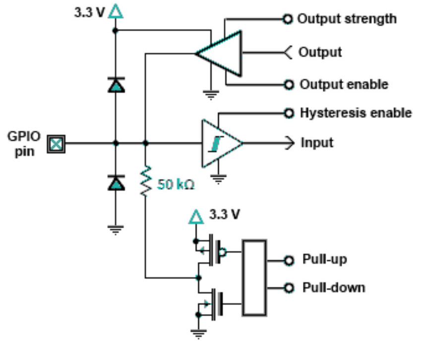
Figure 6 : GPIO pin logic
The control pad top and spacers were laser cut from 3mm acrylic sheet, the bottom from 1mm nylon sheet. This produced the perfect thickness for 12mm M3 bolts. The CAD file can be downloaded here: (Link). One small mistake, forgot the LED holes :), these were drilled out later. Also filed out a slot in the acrylic spacer for the ribbon cable and rounded the edges of the acrylic sheets, as these can be quite sharp i.e. to help protect the ribbon cable. If i was to make it again i would of redone the back to remove the switch holes.
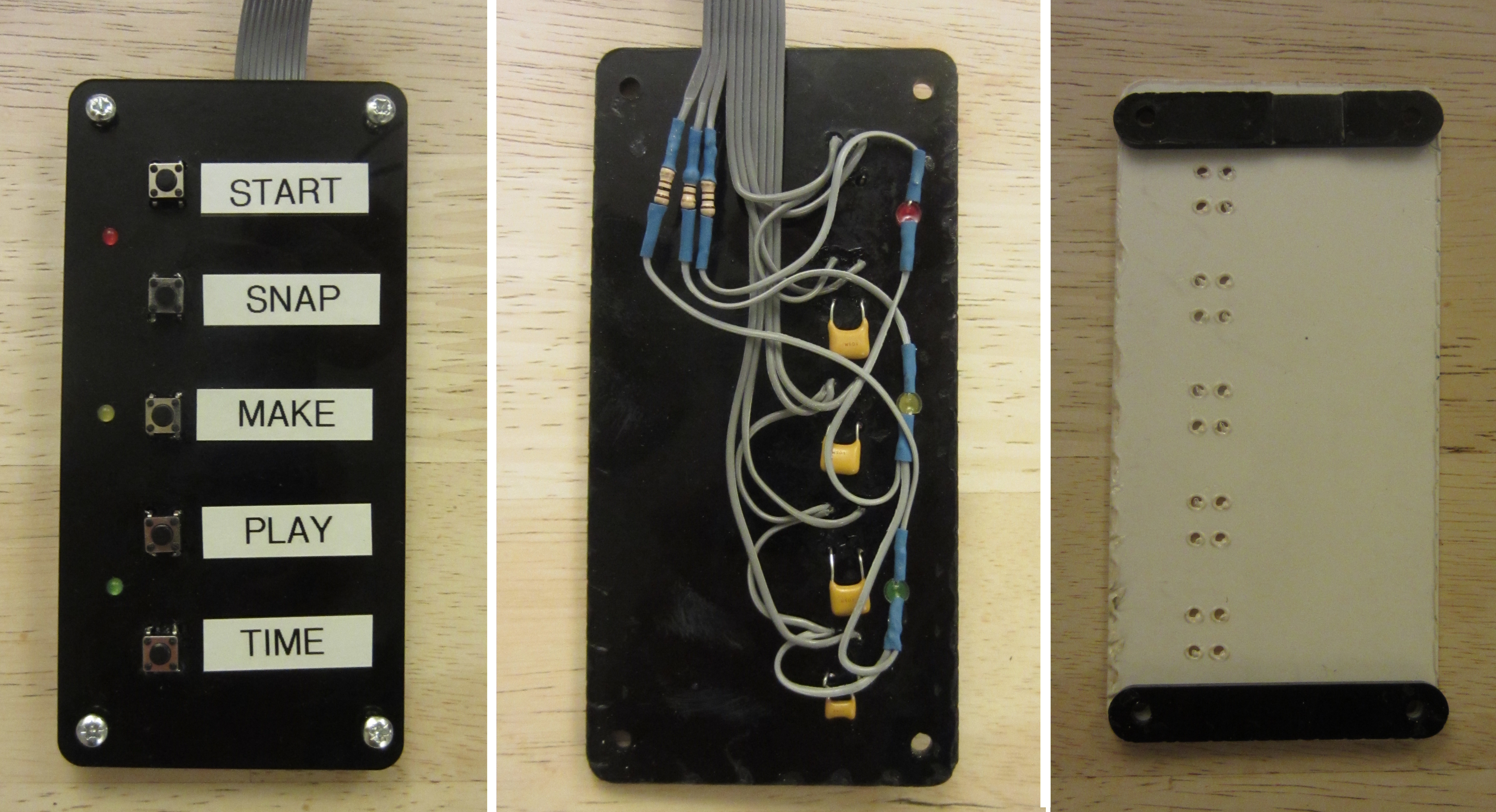
Figure 7 : Control pad
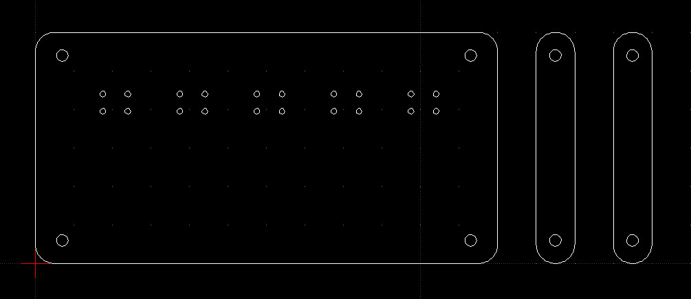
Figure 8 : Control pad drawings
The web camera did originally come with a small tripod, shown in figure 9, but from initial testing it was a little low, so decided to print out a tripod (Link). This tripod was originally designed for a SLR camera, so the mounting hole was a little large, simple fix was to fill it with Milliput to form a shaped mounting socket. Milliput is a two part Epoxy putty, when mixed it curses over a couple of hours to a very solid material, excellent for filling holes (actually very strong). The web camera was easily removed from its original mount, single self tapper screw on the bottom.
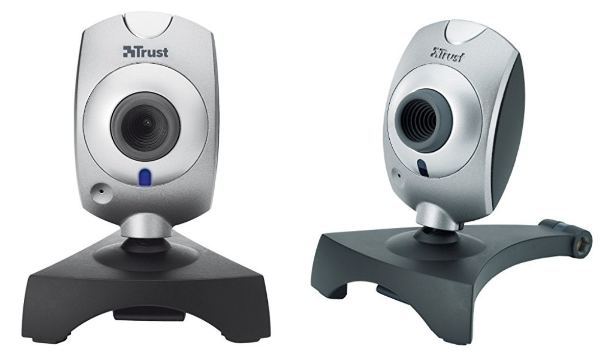
Figure 9 : Camera
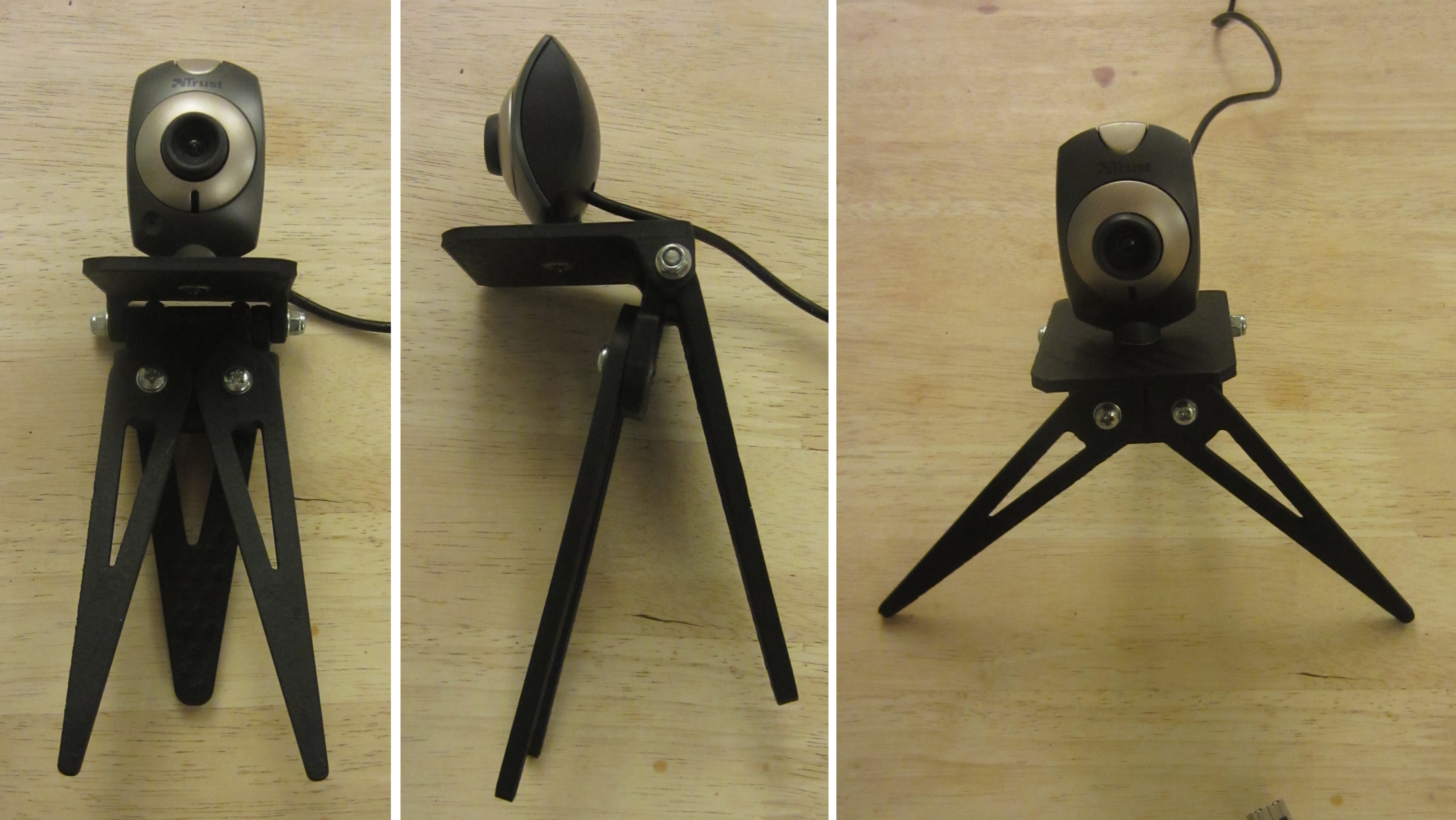
Figure 10 : Tripod

Figure 11 : Milliput
I would describe my software solution as an inspired mixture of shell script and Python :). Part of the reason for the mix is quite a lot of the functionality is implemented from command line instructions. Software packages to install:
apt-get install fswebcam
apt-get install camorama
apt-get install libavtools
The main control software is implemented in Python, each switch is association to an event, triggering a shell script program. Not sure if the sleep function is needed in the main loop, but decided to put something in it. Switch functions are:
The Python to implement this is shown in figure 12. As previously discussed the callback functions have a debounce attribute of 500ms i.e. once triggered the event is disabled for this time. As a switch's contact bounce normally lasts for less than 50ms, this should of solved the problem, however, no joy, to be honest starting to think there is a bug in the code. The first four switches are a single trigger functionality. The time lapse switch is a toggle, when first triggered the shell script code writes the file "time-lapse-start", therefore, first time through it doesn't exist, turning on the LED. Also the shell script is launched using '&', allowing it to run in the background, so that the Python program can continue. Second time the button is pressed the file is detected, turning off the LED.
import RPi.GPIO as GPIO 				#IO library
import time 						#Time library
import os						#system calls

def sw_a_pressed( pin ):
        GPIO.output(13, True) 				#RED LED on
	print("sw a pressed - delete images")		#debug message
        os.system("/home/pi/Animation/start.sh")	#run shell script
        time.sleep(1)					#delay
        GPIO.output(13, False) #RED			#RED LED off

def sw_b_pressed( pin ):
        GPIO.output(12, True) 				#YELLOW LED on
	print("sw b pressed - take image")		#debug message
        os.system("/home/pi/Animation/snap.sh")		#run shell script
        time.sleep(1)					#delay
        GPIO.output(12, False) 				#YELLOW LED off

def sw_c_pressed( pin ):
        GPIO.output(6, True) 				#GREEN LED on
	print("sw c pressed - generate video")		#debug message
        os.system("/home/pi/Animation/animate.sh")	#run shell script
        time.sleep(1)					#delay
        GPIO.output(6, False) 				#GREEN LED off

def sw_d_pressed( pin ):
	print("sw d pressed - play video")		#debug message
        os.system("/home/pi/Animation/play.sh")		#run shell script
        time.sleep(1)					#delay

def sw_e_pressed( pin ):

        if (os.path.isfile("/home/pi/Animation/time-lapse-start")):	#use sync file to implement a toggle
                GPIO.output(13, False) 			#RED LED off
        else:
                GPIO.output(13, True) 			#RED LED on

	print("sw e pressed - time lapse")		#debug message
	os.system("/home/pi/Animation/time-lapse.sh &")	#run shell script
        time.sleep(1)					#delay

GPIO.setwarnings(False) 				#disable runtime warnings
GPIO.setmode(GPIO.BCM) 					#use Broadcom GPIO names

GPIO.setup(16, GPIO.IN, pull_up_down=GPIO.PUD_UP)   # SW A
GPIO.setup(19, GPIO.IN, pull_up_down=GPIO.PUD_UP)   # SW B
GPIO.setup(21, GPIO.IN, pull_up_down=GPIO.PUD_UP)   # SW C
GPIO.setup(20, GPIO.IN, pull_up_down=GPIO.PUD_UP)   # SW D
GPIO.setup(26, GPIO.IN, pull_up_down=GPIO.PUD_UP)   # SW E

GPIO.add_event_detect(16, GPIO.FALLING, callback=sw_a_pressed, bouncetime=500)
GPIO.add_event_detect(19, GPIO.FALLING, callback=sw_b_pressed, bouncetime=500)
GPIO.add_event_detect(21, GPIO.FALLING, callback=sw_c_pressed, bouncetime=500)
GPIO.add_event_detect(20, GPIO.FALLING, callback=sw_d_pressed, bouncetime=500)
GPIO.add_event_detect(26, GPIO.FALLING, callback=sw_e_pressed, bouncetime=500)

GPIO.setup(13, GPIO.OUT)	# LED output
GPIO.setup(6, GPIO.OUT)		# LED output
GPIO.setup(12, GPIO.OUT)	# LED output

GPIO.output(13, False) 		#RED LED
GPIO.output(6, False) 		#GREEN LED
GPIO.output(12, False) 		#YELLOW LED

while True:			# main loop
	time.sleep(100)
Figure 12 : Control software
SNAP.SH: the initial IF stops this program running multiple times. The next IF tests if the file "count.txt" exists. First time through the it creates the file and writes 0, then subsequent times it increments this value (COUNT). Finally the file name is generated based on this value, padded with 0s to create a four digit number. The picture is taken using fswebcam, the -S parameter skips the first four images, this is needed occasionally as the first image from this web camera can be misaligned.
#!/bin/sh

#is program running?
if test -f /home/pi/Animation/snapping
then
	echo snapping
else
	echo > /home/pi/Animation/snapping

	#does count file exist
	if test -f /home/pi/Animation/count.txt
	then
   		COUNT=`cat /home/pi/Animation/count.txt`
	else
   		echo 0 > /home/pi/Animation/count.txt
   		COUNT=0
	fi

	#generate filename
	if test $COUNT -gt 999
	then
   		FILENAME=pic_$COUNT.jpg
	elif test $COUNT -gt 99
	then
   		FILENAME=pic_0$COUNT.jpg
	elif test $COUNT -gt 9
	then
   		FILENAME=pic_00$COUNT.jpg
	else
   		FILENAME=pic_000$COUNT.jpg
	fi

	#echo $FILENAME

	#capture image
	fswebcam -d /dev/video0 -r 640x480 -S 4 --no-banner /home/pi/Animation/$FILENAME

	#increment count
	COUNT=$(($COUNT + 1))
	echo $COUNT > /home/pi/Animation/count.txt

	#remove sync file
	sleep 0.5
	rm /home/pi/Animation/snapping
fi
ANIMATE.SH: the first second generates a file name based on the date and time. After initial testing i found that if you try and generate a video with less than 20-ish pictures it locks up the video player. Therefore, the shell script program calculates the name of the last picture and replicates this 20 times. The program avconv then converts these pictures into a mp4 video.
#!/bin/sh

#create filename
DATE=`date | tr -s " "`
MONTH=`echo $DATE | cut -d' ' -f2`
DAY=`echo $DATE | cut -d' ' -f3`
TIME=`echo $DATE | cut -d' ' -f4`
YEAR=`echo $DATE | cut -d' ' -f6`

#echo $TIME $DAY $MONTH $YEAR

VIDEO="video_$DAY$_MONTH_$YEAR_$TIME.mp4"
echo $VIDEO

#calc padding files
LAST=`ls /home/pi/Animation/pic_*.jpg | head -1`
COUNT=`ls /home/pi/Animation/pic_*.jpg | grep -c pic`
echo $LAST $COUNT

#generate files
for count in `seq 1 20`
do
	if test $COUNT -gt 999
	then
   		FILENAME=pic_$COUNT.jpg
	elif test $COUNT -gt 99
	then
   		FILENAME=pic_0$COUNT.jpg
	elif test $COUNT -gt 9
	then
   		FILENAME=pic_00$COUNT.jpg
	else
   		FILENAME=pic_000$COUNT.jpg
	fi

	cp $LAST /home/pi/Animation/$FILENAME
	COUNT=$(($COUNT + 1))
done
sleep 1

#generate video
avconv -y -i /home/pi/Animation/pic_%04d.jpg -s 320x240 -r 10 -vcodec libx264 /home/pi/Animation/$VIDEO
cp -f /home/pi/Animation/$VIDEO /home/pi/Animation/video.mp4
PLAY.SH: simple one, launches omxplayer
#!/bin/sh

omxplayer /home/pi/Animation/video.mp4
TIME.SH: time lapse video. The associated switch toggles this function on/off. To indicate the state of this function sync files are used: "time-lapse-start" and "time-lapse-stop". First time through the file "time-lapse-start" is not present, starting the recording sequence FOR loop, taking a picture every 30 seconds. The second time this shell script is called the file "time-lapse-stop" is created stopping the time lapse sequence.
#!/bin/sh

if test -f /home/pi/Animation/time-lapse-start
then
	echo > /home/pi/Animation/time-lapse-stop
else
	echo > /home/pi/Animation/time-lapse-start

	for count in `seq 1 1000`
	do
		/home/pi/Animation/snap.sh
		sleep 30

		if test -f /home/pi/Animation/time-lapse-stop
		then
			rm /home/pi/Animation/time-lapse-stop /home/pi/Animation/time-lapse-start
			break
		else
			echo > /home/pi/Animation/time-lapse-start
		fi
	done
fi
START.SH: removes all photos taken and sync files: snapping, time-lapse-stop, time-lapse-start. To ensure that the time lapse function is stopped the PID number is identified then killed.
#!/bin/sh
rm -f /home/pi/Animation/count.txt
rm -f /home/pi/Animation/pic*.jpg
rm -f /home/pi/Animation/focus.jpg
rm -f /home/pi/Animation/snapping
rm -f /home/pi/Animation/time-lapse-stop
rm -f /home/pi/Animation/time-lapse-start

PID=`ps -ax | grep Animation | tr -s ' ' | grep time | cut -d' ' -f2`
kill $PID
GO.SH: this shell script is launched by the cron at boot i.e. @reboot /home/pi/Animation/go.sh. StdGPIO, StdERR are redirected into files for debugging.
#!/bin/sh
python /home/pi/Animation/control.py 1> /home/pi/Animation/control.log 2> /home/pi/Animation/control.err &
To test the system made this small movie, pictures available here:(Link), video here: (Link).

Figure 13 : Bug

This work is licensed under a Creative Commons Attribution-NonCommercial-NoDerivatives 4.0 International License.
Contact details: email - mike.freeman@york.ac.uk, telephone - 01904 32(5473)
Back