Our research
Battery Electrochemical Models
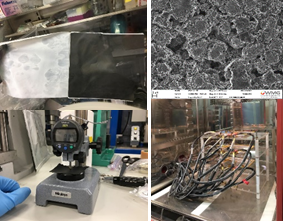
In this project we developed a 1D electrochemical-thermal coupled with a 3D thermal model to characterise the behaviour of a 53 Ah large format pouch cell with NMC chemistry over a wide range of operating conditions, including: continuous charge (0.5C-2C), continuous discharge (0.5C-5C) and operation of the battery within an electric vehicle (EV) over an urban drive-cycle (WLTP Class 3) and for a high performance EV being driven under track racing conditions.
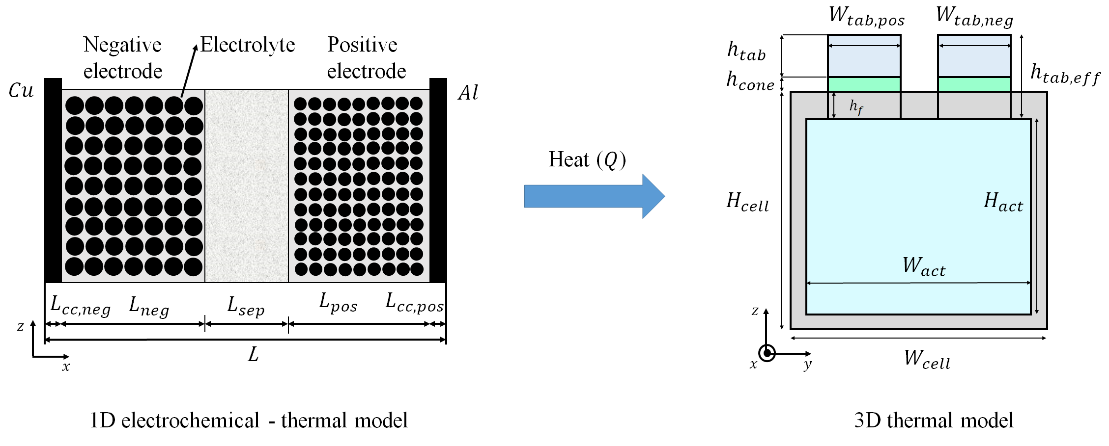
1D Electrochemical-Thermal Model coupled with a 3D Thermal model (link to the paper)
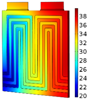
Formulation of the model is supported by a comprehensive set of experiments, for quantifying key parameters and for model validation. Overall, response dependency of lithium-ion battery to operating conditions underpins the value of the detailed performance of the cell under specific conditions. For example, safety and reliability of the cell can be improved, knowing how quickly the cell reaches to the cut-off temperature so that potential hazards such as thermal runaway can be avoided. Moreover, the existing correlation between the temperature and the achievable capacity, power and usable lifetime can help us extend the vehicle range and reduce the cost of the battery pack.
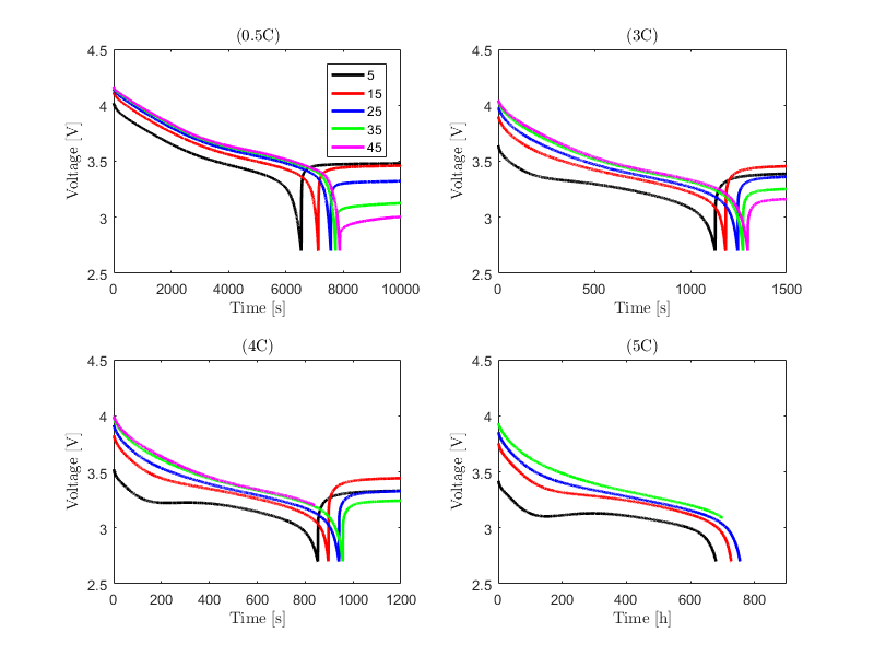
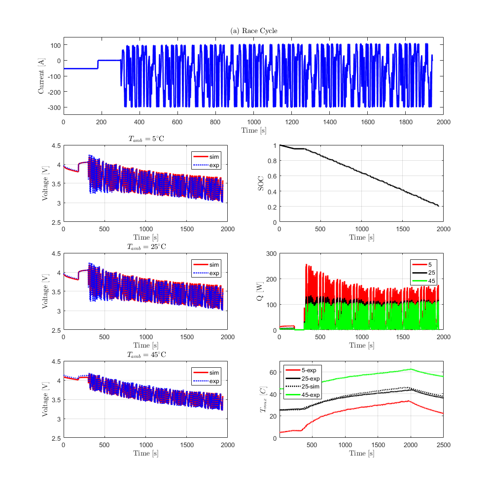
Validated numercial results (voltage and temperature profiles), for a 53 Ah cell
Battery Design Optimisation
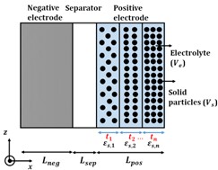
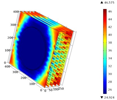
In this work a P2D model is validated for a 10 Ah LFP pouch cell operating under 1C-5C at 25°C ambient temperature. The validated model is used to conduct statistical analysis of the most influential parameters that dictate cell performance; i.e., particle radius (rp); electrode thickness (Lpos); volume fraction of the active material (eps_pos) and C-rate; and their interaction on the two main responses; namely; specific energy and specific power.
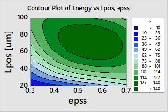
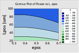
Contour plot of the specific energy and power (link to the paper)
Using a P2D electrochemical approach coupled with a 1D and 3D lumped thermal model, this study presents a fully validated model of a large format 53 Ah for a wide range of continuous charge (0.5C-2C), discharge (0.5C-5C), and drive cycles (race cycle and WLTP class 3), under 5°C–45°C ambient temperature. Formulation of the model is
Battery Multi-Layered Structure
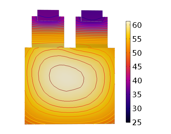
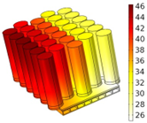
This study investigates the impact of a multi-layered porosity profile on the electrical and thermal performance of a lithium-ion battery. The COMSOl Multiphysics software tool has been employed to develop a 3D electrochemical-thermal model of a commercially available 10 Ah lithium iron phosphate cell. Through an extensive simulation study, for a fixed value of active material, the impact of varying the porosity profile across both the thickness and height of the electrode has been studied. The simulation results highlight that a multi-layered porosity distribution along the electrode thickness, with high porosity at the separator/electrode interface, seems to yield the most promising results.
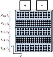
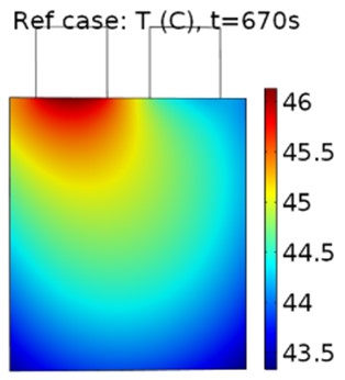
Multi-layered structure of porosity across the electrode thickness and height (link to the paper)
Battery Pack Models
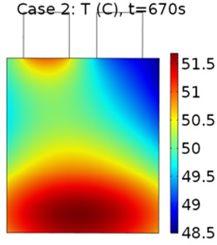
Cell-to-cell variations can originate from manufacturing inconsistency or poor design of the battery pack/thermal management system. The potential impact of such variations may limit the energy capacity of the pack, which for electric vehicle applications leads to reduced range, increased degradation along with state of health (SoH) dispersion within a pack. The latter is known to reduce the accessible energy and the overcharging/discharging of some of the cells within a system, which may cause safety concerns. This study investigates the short-term impact of such effects, which is highly important for designing of an energy storage system (ESS). A generic pack model comprising individual cell models is developed and validated for a 1s-15p module architecture.
Battery pack configurations (link to the paper)
Battery Thermal Management
A Lithium ion batteries have an optimum range of operating temperature (15-35 °C), within which they have the best performance. In addition, the temperature gradient of the battery in both the cell level and pack level should be kept lower than 5 °C to reduce the degradation rate. Battery characteristics such as power and energy density, cycle life, reliability and cost are strongly affected by their operating temperature. Therefore, a proper thermal management system is required to ensure a safe operation as well as prolonged lifetime.
Battery cell/module thermal management (link to the paper)
Hybrid Battery/Fuel Cell Powertrain
The performance of a forklift truck powered by a hybrid system consisting of a PEM fuel cell and a lead acid battery has been modeled and investigated by conducting a parametric study. Various combinations of fuel cell size and battery capacity were employed in conjunction with two distinct control strategies to study their effect on hydrogen consumption and battery state-of-charge for two drive cycles characterized by different operating speeds and forklift loads. The results showed that for all case studies, the combination of a 110 cell stack with two strings of 55 AH batteries was the most economical choice for the hybrid system based on system size and hydrogen consumption.
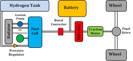
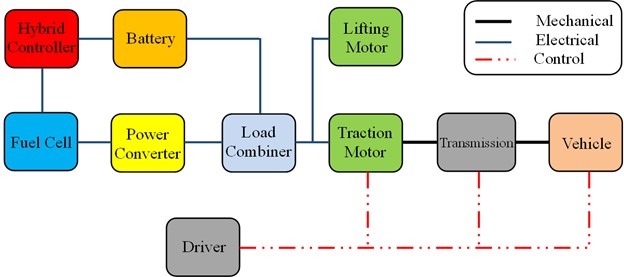
Schematic of the System (link to the paper)
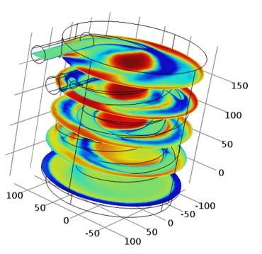
Fuel Cell Design
The main goal here is to develop a more efficient fuel cell stack considering channel design, manifold, operating conditions and other key parameters. We developed different zero-dimentional, 2D/3D models using various software packges (Excel, MATLAB/Simulink, COMSOL MULTIPHYSICS) to imrpove the heat and mass transfer within the fuel cell channels and ultimatelly increase the system efficiency. Some examples are shwon here:
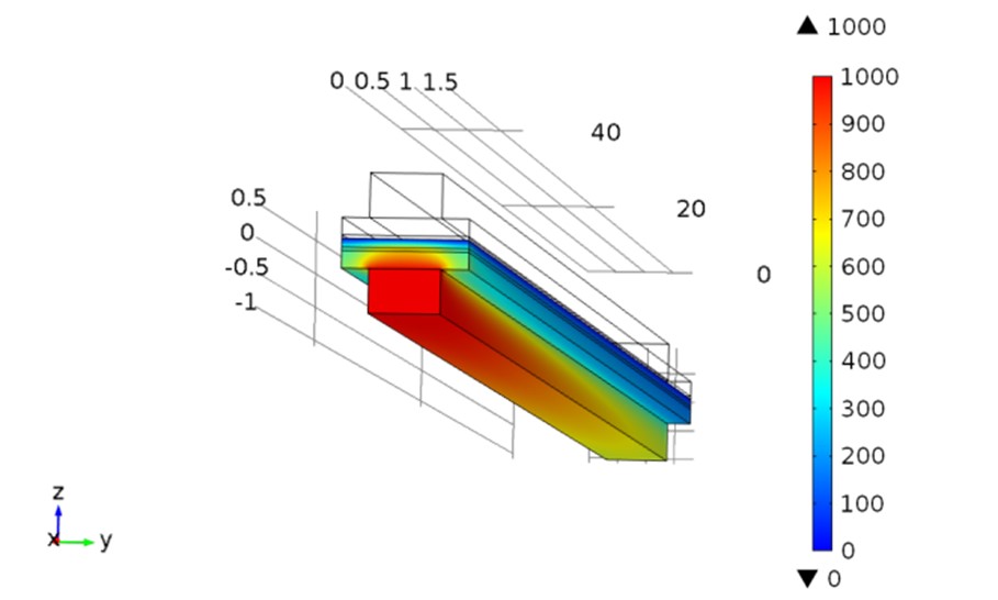
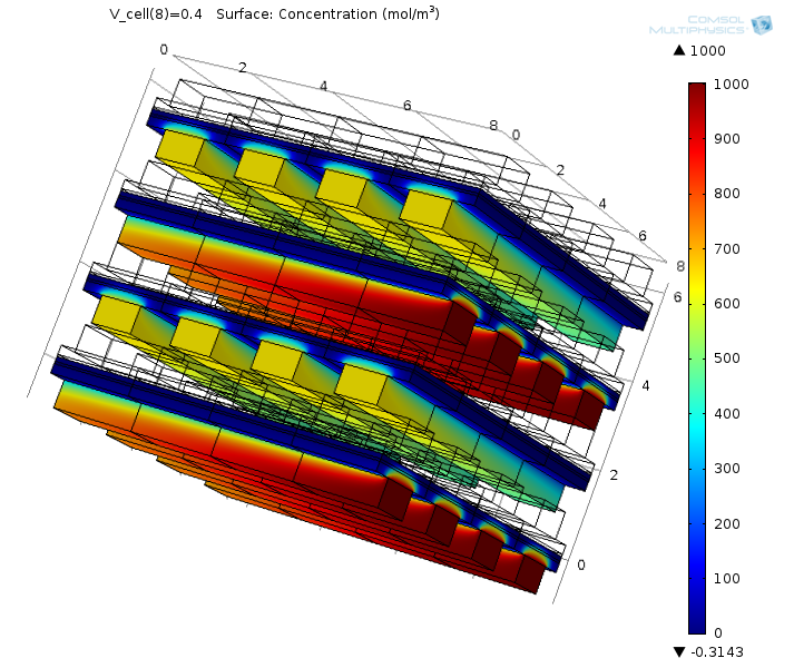
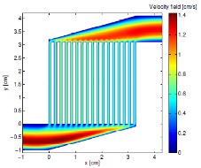
DMFC (Direct Methanol Fuel Cell), single channel and manifold
Ejector Design for PEMFC Hydogen Recirculation Loop
In this study, Computational Fluid Dynamics (CFD) technique is used to design an ejector for anode recirculation in an automotive PEMFC system. A CFD model is firstly established and tested against well-documented and relevant solutions from the literature, and then used for different ejector geometries under different operating conditions.
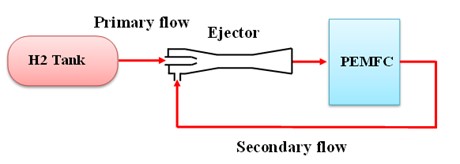
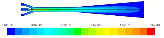
Ejector design (link to the paper)
Heat Exchange Design for a Fuel Cell System
In this study, Computational Fluid Dynamics (CFD) technique is used to design an ejector for anode recirculation in an automotive PEMFC system. A CFD model is firstly established and tested against well-documented and relevant solutions from the literature, and then used for different ejector geometries under different operating conditions.
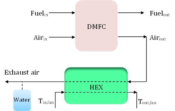
Heat exchanger design
Fuel Cell System
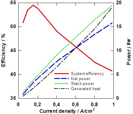
A general zero dimentional PEMFC (Proton Exchange Membrane Fuel Cell) model has been developed for the application in a forklift truck system. The BOP (Balance of Plant) comprises a compressor, an air humidifier, a set of heat exchangers and a recirculation pump. Water and thermal management of the fuel cell stack and BOP has been investigated in this study. The results show that humidification of the inlet air is of great importance. By decreasing the relative humidity of the inlet air from 95 to 25%, the voltage can even drop by 29%.
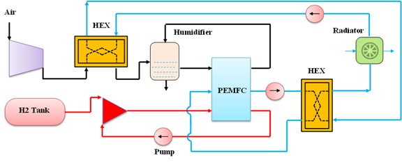
Fuel cell system (link to the paper)